Focal shift
Focal shift
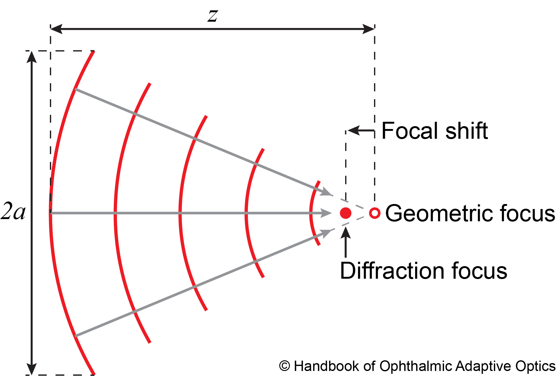
There are two points of interest near the focus of a converging spherical wavefront. The geometrical focus, where the rays orthogonal to the wavefront converge (see figure below), and the point of maximum intensity, which is shifted towards the incoming wavefront due to diffraction, and it is therefore referred to as the diffraction focus. The distance between these two foci, that is, the focal shift (\(\Delta z\)), is a function of the Fresnel number \(N = a^2 / \lambda z\), where \(a\) is the beam radius at a distance \(z\) to the geometrical focus and \(\lambda\) is the light wavelength.
Yajun Li (Eq. 3.12) derived an approximate formula for the focal shift of a rotationally symmetric converging wavefront when \(N \geq 0.5\) and \(F \geq 1\),
where the f-number of the beam, \(F = z / 2a\). The negative sign indicates that the diffraction focus is always shifted towards the converging wavefront. Colin J. R. Sheppard and Peter Török (Eq. 17) arrived at a simpler formula for high numerical aperture systems with small focal shifts,
where \(\alpha = \sin^{-1}(a/z)\).
Download code here:
- Matlab - focal shift calculator function
- Matlab - script demonstrating its use
- Python - focal shift calculator function
- Python - script demonstrating its use
Focal shift calculator
Focal shift in the Shack-Hartmann wavefront sensor
When a positive lens free of wavefront aberrations is normally illuminated with a plane wave, the Fresnel number, and thus the focal shift can be calculated n in terms of the lens clear aperture diameter \(D_L\) and its back (geometrical) focal length \(f_L\). In most imaging applications, however, the relative focal shift \(\Delta f_L / f_L\) is negligible. For example, in a typical human eye \( f_{\textrm{eye}}\approx\)16.7 mm imaged with a conventional optical coherence tomgrapher \(D_{\textrm{beam}} \approx\)1.0 mm using 850 nm light, \(\Delta f_{\textrm{eye}} / f_{\textrm{beam}} \approx \)-0.4%. If, on the other hand, we consider a typical Shack-Hartmann wavefront sensor lenslet with 200 um diameter and 8 mm focal length, we have that the relative focal shift is approximately 29-36%, which is not negligible.
Now the important question is, why should we care about the focal shift in a Shack-Hartmann wavefront sensor? Because if the pixelated detector is not placed in the geometrical focus, then the centroid of partially illuminated lenslets will be biased in a wavefront-independent manner. This can be solved by ignoring partially illuminated lenslets in the wavefront estimation or reconstruction algorithm, but that could be problematic if the wavefront illuminating the Shack-Hartmann wavefront sensor lenslet array does not have a uniform intensity profile. A more elegant, and arguably simple, solution is to put the pixelated sensor in the geometrical focal plane of the lenslet array, as demonstrated by V. Akondi and A. Dubra. The proposed pixelated sensor focusing approach does not require the calculation of the focal shift, but rather allows finding the geometrical focus by empirically minimizing centroid bias using a test wavefront.